What's new

Rytec Wyndstar Issue

SparklesSS

Member
Joined
May 6, 2019
Messages
66
Reaction score
2
Points
8
Frustrating issue with one of my Rytec Wyndstar doors. Everything works fine except the photo eyes, they will not detect an obstruction and the door will come all the way down. Changed both the emitter and receiver as well as the cables going into the control board. Nothing seems to fix the issue. I am at a loss....Anyone have any suggestions??

Thanks in advance
 

JGinther

Zip-tie engineer
Joined
May 31, 2008
Messages
743
Reaction score
172
Points
43
Location
Loveland, CO
The limit switch might not be set right for the eye. They signal from the eye is wired through a limit cam. Typically it's set to work until the door reaches the height of the eye.
 

SparklesSS

Member
Joined
May 6, 2019
Messages
66
Reaction score
2
Points
8
The limit switch might not be set right for the eye. They signal from the eye is wired through a limit cam. Typically it's set to work until the door reaches the height of the eye.
Thanks. How might I confirm this? The door was working prior to the last few weeks.
 

JGinther

Zip-tie engineer
Joined
May 31, 2008
Messages
743
Reaction score
172
Points
43
Location
Loveland, CO
You could wire around the limit switch. Just follow the wires up to the limit and wire the signal wire to the control board instead of the cam/limit. Are the correct sensors installed? Have they been switched?
 

Rudy

Active member
Joined
Sep 5, 2007
Messages
722
Reaction score
112
Points
43
Location
Pennsylvania
I have a VERY early Wyndstar door. It has an external panel that contains the Photoeye amplifiers, relays etc. Later models have the electronics mounted integral with the motor.

Anyway....I had a similar issue when one of the cube relays went bad. This relay is the one that "clicks" when the photo eye gets broken. I also had to replace the photo eye amplifier once.

If you have the integral electronics....I can't help you.

Do you have the internal or external type?
 

SparklesSS

Member
Joined
May 6, 2019
Messages
66
Reaction score
2
Points
8
I have a VERY early Wyndstar door. It has an external panel that contains the Photoeye amplifiers, relays etc. Later models have the electronics mounted integral with the motor.

Anyway....I had a similar issue when one of the cube relays went bad. This relay is the one that "clicks" when the photo eye gets broken. I also had to replace the photo eye amplifier once.

If you have the integral electronics....I can't help you.

Do you have the internal or external type?
Internal
 

SparklesSS

Member
Joined
May 6, 2019
Messages
66
Reaction score
2
Points
8
You could wire around the limit switch. Just follow the wires up to the limit and wire the signal wire to the control board instead of the cam/limit. Are the correct sensors installed? Have they been switched?
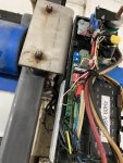
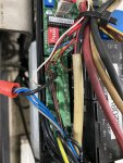
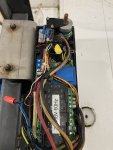
I do not have a good diagram.Which wires are the limit and signal? Sensors are installed correctly and switched to new ones. Also installed a new cable to the receiver. I’ll post pictures.
 

JGinther

Zip-tie engineer
Joined
May 31, 2008
Messages
743
Reaction score
172
Points
43
Location
Loveland, CO
Where do the grey wires in the nut go? Are they the third wire in the cable going to the sensors? Are you sure you have the correct sensors? They need to be PNP type for Windstar doors I'm pretty sure. Trying to judge by the pictures, it appears the limit would be the grey cam that has the red and white wire connected - above the board. If its wired how they meant for it to work, it would be like this:
Both (emitter and receiver - even though only receiver wire is actually functional) signal wires from the sensors (not blue, not brown - those are power) would wire to the cam switch. The cam would be adjusted so that it would allow the signal to the board when door is up and keep allowing it through travel down until the door reaches the sensor elevation. At that point, the cam would bypass the signal and the door would continue to close even if the eye was to be blocked. Its dumb.
 

SparklesSS

Member
Joined
May 6, 2019
Messages
66
Reaction score
2
Points
8
Where do the grey wires in the nut go? Are they the third wire in the cable going to the sensors? Are you sure you have the correct sensors? They need to be PNP type for Windstar doors I'm pretty sure. Trying to judge by the pictures, it appears the limit would be the grey cam that has the red and white wire connected - above the board. If its wired how they meant for it to work, it would be like this:
Both (emitter and receiver - even though only receiver wire is actually functional) signal wires from the sensors (not blue, not brown - those are power) would wire to the cam switch. The cam would be adjusted so that it would allow the signal to the board when door is up and keep allowing it through travel down until the door reaches the sensor elevation. At that point, the cam would bypass the signal and the door would continue to close even if the eye was to be blocked. Its dumb.
Here is the wire set up:
Brown wires- 24vdc +
Grey and Blue wires- 24vdc -
Black wires- Photo (NC)
Red and White wire- runs from Photo (NC) to limit switch.

Is there a way for me to check to see if the signal from the receiver is making it to the board? Should I bypass the limit switch?

The sensors are the correct ones (same part number, make, and model as recommended.
 

Rudy

Active member
Joined
Sep 5, 2007
Messages
722
Reaction score
112
Points
43
Location
Pennsylvania
Three are 3 limit switches. One for UP limit, One for Down limit,....And....One that bypasses the obstruction signal when closing. This limit switch is set to the height of your photo eyes. Basically (if I understand it correctly)...when the door lowers AND ALSO reaches the level of the photo eye.....any obstruction WILL NOT cause the door to reverse....It continues to close. Because the photo eye is so close to the ground....this shouldn't be a safety issue. This keeps blowing leaves (etc.) from reversing the door when it's almost closed.

Again....I may or may not have the correct understanding.

If this explanation is correct....then I'd begin to look at the so called "bypass" limit switch and corresponding wiring.

It sounds like this switch (or the relay it controls) is signaling that the door is almost closed....when it actually isn't. That's why your door might not be reversing.

Speaking of reversing.....can you reverse the door while it's lowering with the manual controls? That'd be another issue that would involve the reversing circuitry. Not likely...but it'd only take you a few seconds to isolate the problem to the photoeye circuit.
 

SparklesSS

Member
Joined
May 6, 2019
Messages
66
Reaction score
2
Points
8
Three are 3 limit switches. One for UP limit, One for Down limit,....And....One that bypasses the obstruction signal when closing. This limit switch is set to the height of your photo eyes. Basically (if I understand it correctly)...when the door lowers AND ALSO reaches the level of the photo eye.....any obstruction WILL NOT cause the door to reverse....It continues to close. Because the photo eye is so close to the ground....this shouldn't be a safety issue. This keeps blowing leaves (etc.) from reversing the door when it's almost closed.

Again....I may or may not have the correct understanding.

If this explanation is correct....then I'd begin to look at the so called "bypass" limit switch and corresponding wiring.

It sounds like this switch (or the relay it controls) is signaling that the door is almost closed....when it actually isn't. That's why your door might not be reversing.

Speaking of reversing.....can you reverse the door while it's lowering with the manual controls? That'd be another issue that would involve the reversing circuitry. Not likely...but it'd only take you a few seconds to isolate the problem to the photoeye circuit.
yes, with the manual control buttons I can reverse, stop, lower the door. It is also wired to raise the door 30 seconds after someone enters the bay if they do not put money in to activate the bay. It also raises at the end of the wash. All these functions are working, just not the photo eye.
 

Rudy

Active member
Joined
Sep 5, 2007
Messages
722
Reaction score
112
Points
43
Location
Pennsylvania
I'd start by eliminating the bypass limit switch. I don't know if it works as normally open or normally closed.....I think mine is wired normally open. Remove the wire from the bypass limit switch....and see how that affects the photoeye operation.

I bet that the microswitch has either failed open or failed closed. Get an ohmeter and check.
 

SparklesSS

Member
Joined
May 6, 2019
Messages
66
Reaction score
2
Points
8
I'd start by eliminating the bypass limit switch. I don't know if it works as normally open or normally closed.....I think mine is wired normally open. Remove the wire from the bypass limit switch....and see how that affects the photoeye operation.

I bet that the microswitch has either failed open or failed closed. Get an ohmeter and check.
which wire should I remove? The red, white or both? Should they be connected to another place?
 

Rudy

Active member
Joined
Sep 5, 2007
Messages
722
Reaction score
112
Points
43
Location
Pennsylvania
I can't tell from your picture. It looks like you have 4 limit switches. I'd bet that only 3 are wired (or in use). Trace the wires back to the end of the board. There's a 7 contact strip (abeam the 2 blue adjustable resistors). The left (first) contact is for close, the second is for open....and the third is the common. The wire from the first should track to the close limit switch, the second wire should track back to the open limit switch. The remaining limit switch should be the bypass one.

Am I correct that only 3 limit switches are wired?
 

JGinther

Zip-tie engineer
Joined
May 31, 2008
Messages
743
Reaction score
172
Points
43
Location
Loveland, CO
You wrote NC for the black photo sensor wires... Does that mean not connected? I think I see a black wire connected to the photo input on the board. That should be your 'signal' wire. Then you would just unhook the red and white wires to eliminate the limit switch overriding the photo eye signal. I can't remember for sure, but I think the door can be set up to have the eye open the door when blocked. The limit override prevents someone just walking up to the door and opening it by blocking the eye or the door opening if an eye gets snow on it or randomly fails. In other words, the eye can work as a presence sensor opener also (think forklifts at factories needing to go through a curtain wall). Removing the red and white wires should allow they eye to work for now for troubleshooting. After that, you would know to either adjust the limit if it's set wrong, or fix the microswitch.
 
Last edited:

Rudy

Active member
Joined
Sep 5, 2007
Messages
722
Reaction score
112
Points
43
Location
Pennsylvania
I agree. The more I look....it appears that the top limit switch (with the red and white wires)....is your "bypass" limit switch. It appears that the red and/or white wires attach somewhere close to the board....labeled PHOTO.

Unhook the red and white wire at the limit switch. I bet nothing changes. Connect the red and white wire (from the bypass limit switch) with a jumper. I bet your photoeye starts working OK. If so....the microswitch in the bypass limit is bad.

As always.....remove/jumper things at your own risk. I don't think you'll be damaging anything....but it's hard to troubleshoot via a picture......
 

SparklesSS

Member
Joined
May 6, 2019
Messages
66
Reaction score
2
Points
8
You wrote NC for the black photo sensor wires... Does that mean not connected? I think I see a black wire connected to the photo input on the board. That should be your 'signal' wire. Then you would just unhook the red and white wires to eliminate the limit switch overriding the photo eye signal. I can't remember for sure, but I think the door can be set up to have the eye open the door when blocked. The limit override prevents someone just walking up to the door and opening it by blocking the eye or the door opening if an eye gets snow on it or randomly fails. In other words, the eye can work as a presence sensor opener also (think forklifts at factories needing to go through a curtain wall). Removing the red and white wires should allow they eye to work for now for troubleshooting. After that, you would know to either adjust the limit if it's set wrong, or fix the microswitch.
NC is what is in brackets on the board. I will go today and get better pictures. Is there a way to test the signal wire to make sure the receiver is sending the signal?
 

SparklesSS

Member
Joined
May 6, 2019
Messages
66
Reaction score
2
Points
8
I agree. The more I look....it appears that the top limit switch (with the red and white wires)....is your "bypass" limit switch. It appears that the red and/or white wires attach somewhere close to the board....labeled PHOTO.

Unhook the red and white wire at the limit switch. I bet nothing changes. Connect the red and white wire (from the bypass limit switch) with a jumper. I bet your photoeye starts working OK. If so....the microswitch in the bypass limit is bad.

As always.....remove/jumper things at your own risk. I don't think you'll be damaging anything....but it's hard to troubleshoot via a picture......
I will go today and get better pictures. Is there a way to test the signal wire to make sure the receiver is sending the signal?

should I try to connect the white and red wire? Is there a risk of harming anything?
 
Top