What's new

Help wiring a LP panel

MEP001

Well-known member
Joined
Aug 30, 2007
Messages
16,665
Reaction score
3,946
Points
113
Location
Texas
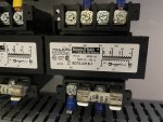
Is it possible to move or change the transformer inputs to different positions to get them in phase with each other?
If the outputs are out of phase, it's because the inputs are also out of phase. That's how I correct it - sometimes even the 3-phase to the motors aren't properly matched up, not that it matters, but when the power for the transformers taps out of the motor starters you have to correct them all.
 

Noob

Active member
Joined
Oct 11, 2018
Messages
311
Reaction score
28
Points
28
Location
TN
I’ll check the voltage on the outputs tomorrow. If I install an isolation relay do I need 1 for each bay so 4 total? Does anyone have a link for isolation relay that will work?
 

2Biz

Thread Killer!
Joined
Nov 22, 2010
Messages
2,826
Reaction score
435
Points
83
Location
Ohio
I use Idec RH1B-U relays with a SH1B-05 base and usually find them on Ebay for cheap. They are rated at 10a with over a million life cycles when powering solenoids with only about 6 watts.

The only difference between what I use and what Mep linked to is if one of my relays goes bad (Which I've never had one fail) all I have to do is replace the cube. No wiring...Only takes seconds to replace. The ones above have to be rewired when they need replaced.

This is what they look like after doing a quick search on Ebay.

Idec RH1B-U Relay 24VAC Lot of 7! + 120VAC Lot of 2! | eBay
 

MEP001

Well-known member
Joined
Aug 30, 2007
Messages
16,665
Reaction score
3,946
Points
113
Location
Texas
You can replace the relay in the one I linked, but it costs much more than the whole unit. I doubt it would ever fail with almost no load on it.
 

2Biz

Thread Killer!
Joined
Nov 22, 2010
Messages
2,826
Reaction score
435
Points
83
Location
Ohio
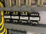
The 12 Idec relays you see in this photo are used as isolation relays between bay input and my winterizing system. This was before I learned about how to phase transformers! I should have done a little more research!! Would have saved me a few $$$ and quite a bit of time wiring it all up!


MEP001

Well-known member
Joined
Aug 30, 2007
Messages
16,665
Reaction score
3,946
Points
113
Location
Texas
This is what I've used in the past:


I haven't used the slim relays I linked above, but I plan to try them on my next project.

I have used the Siemens version of those IDEC relays for a trifoam system and they work to not only control the colors and outputs for 4 solenoids, it also works as a multiplexer. I've used dozens of them with combined commons and each "hot" to an input.
 

cantbreak80

Maybe I need new clubs
Joined
Feb 10, 2008
Messages
1,131
Reaction score
582
Points
113
Location
CO
Noob...
As 2Biz stated...Do yourself a favor and phase the transformers. You’ll thank us if you ever have to do any troubleshooting.
Isolation relays add needless cost and complexity to your systems.

Mep001
Those slim relays look just like Phoenix Contact’s.
Want a nightmare? I’ve replaced too many Phoenix’s to count...they tend to fail closed!
I’ll happily send you my remaining inventory 🙄 (use at your own risk)
 

MEP001

Well-known member
Joined
Aug 30, 2007
Messages
16,665
Reaction score
3,946
Points
113
Location
Texas
They are the same style. I searched the part # on the side of the relay element and it went straight to Phoenix Contact's part. I'll be giving these a try soon, I'll let you know if I have problems with them sticking closed.
 

Noob

Active member
Joined
Oct 11, 2018
Messages
311
Reaction score
28
Points
28
Location
TN
More questions.
I checked the voltages today on the transformers. When I tested inputs H4 to H4 and H2 to H2 across any transformer I got 0. When I tested outputs X1 to X1 I got .5 and X2 to X2 I got 0.

When I tested H2 on one trans and H4 on another trans I got 216. X1 to X2 I got 27.5.

I’m thinking these are in phase based on what MEP said earlier in the thread?

Also the air logic panel shipped with 1/4 fittings for poly tube. I’m thinking of replacing them all with 3/8 fittings. Any cons to this?
 

MEP001

Well-known member
Joined
Aug 30, 2007
Messages
16,665
Reaction score
3,946
Points
113
Location
Texas
I checked the voltages today on the transformers. When I tested inputs H4 to H4 and H2 to H2 across any transformer I got 0. When I tested outputs X1 to X1 I got .5 and X2 to X2 I got 0.

When I tested H2 on one trans and H4 on another trans I got 216. X1 to X2 I got 27.5.
That's exactly how it should be. If you ever change a transformer you should have the same when you're done.

Also the air logic panel shipped with 1/4 fittings for poly tube. I’m thinking of replacing them all with 3/8 fittings. Any cons to this?
In my experience, 1/4" OD tube is plenty for up to 75 feet. It wouldn't hurt to go with 3/8", then the main restrictor will be the solenoid orifice and everything should work more evenly. I usually use 1/4" tubing and have needle valves, and with my wash being over 100' run from solenoid to bay I need to open the far bay valve all the way. The rest are open 3/4 to 1 turn.
 

Noob

Active member
Joined
Oct 11, 2018
Messages
311
Reaction score
28
Points
28
Location
TN
Thanks MEP. Do I need to tie all the commons for the transformers together in order to wire the sir logic?
 

MEP001

Well-known member
Joined
Aug 30, 2007
Messages
16,665
Reaction score
3,946
Points
113
Location
Texas
Yes, and the commons appear to be the X2's.
 

Noob

Active member
Joined
Oct 11, 2018
Messages
311
Reaction score
28
Points
28
Location
TN
Can I just run a connector wire from transformer 1 X2 to transformer 2 X2 to transformer 3 X2 and then to transformer 4 X2 and then run a wire from any of those terminals to the common on the air logic?
 

Noob

Active member
Joined
Oct 11, 2018
Messages
311
Reaction score
28
Points
28
Location
TN
What’s the correct way to tie my commons together?
 

MEP001

Well-known member
Joined
Aug 30, 2007
Messages
16,665
Reaction score
3,946
Points
113
Location
Texas
What’s the correct way to tie my commons together?
It doesn't matter as long as they're all connected. As cb80 said, terminal blocks 2 and 3 are all common. You can see a jumper bus in the center connecting those four together. That would be an easy place to connect them and conceal the wires.

EB3F0BEE-4E28-44F1-919C-88D49FB16863.jpeg
 

cantbreak80

Maybe I need new clubs
Joined
Feb 10, 2008
Messages
1,131
Reaction score
582
Points
113
Location
CO
Then, run a 18ga multi-conductor cable from the CP panel to your Air Logic.
Connect your common to the white wire on the Air Logic terminal strip...it's usually on the right side.

IMG_1297.jpg

I use 1/4" LLDPE tubing out to the bays. Works great for foam brushes and foam guns.
Air Logic provides metered product solenoid manifold and non-metering air solenoids.
I leave the metering valves fully open and adjust the product with the Hydrominder.
Product pressure @ 40 to 45 psi
Air assist pressure @ 28 to 30 psi
A foam generator at the bay works great at smoothing the delivery to foam guns...not necessary for foam brushes.
 
Top