What's new

Help wiring a LP panel

2Biz

Thread Killer!
Joined
Nov 22, 2010
Messages
2,826
Reaction score
435
Points
83
Location
Ohio
Exactly what are you wanting to do?
 

Noob

Active member
Joined
Oct 11, 2018
Messages
311
Reaction score
28
Points
28
Location
TN
I’ve got a new air logic panel that’s going to be used for hot wax. Just trying to figure out how to correctly install the wiring.
 

MEP001

Well-known member
Joined
Aug 30, 2007
Messages
16,665
Reaction score
3,946
Points
113
Location
Texas
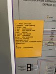
You're going to have to make changes to the rotary switch. Pick what position you want it, choose an unused wire color for it, rearrange the other selections to allow for it, and have a new decal made as well.
 

2Biz

Thread Killer!
Joined
Nov 22, 2010
Messages
2,826
Reaction score
435
Points
83
Location
Ohio
Do you have any duplicate or open selections on your bay rotary switch?
 

Noob

Active member
Joined
Oct 11, 2018
Messages
311
Reaction score
28
Points
28
Location
TN
Yes, I currently have several. I've got 2 offs, a tire and a wheel cleaner which is the same product, and 2 rinses. My current setup is
1. Tire cleaner
2. Wheel cleaner (same product)
3. Presoak
4. HP soap
5. Foamy brush
6. Rinse
7. HP wax
8. Rinse
9. Off
10. Off

I think Id like to move the new function to #7, and then slide HP wax do #8, and the move rinse to the #9 spot.

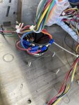
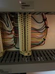
I just need some clarification just make sure I'm doing things correctly. My 24v hot wire that runs to the new panel is going to come off the left side of my terminal pictured above? For instance, Ill run a wire out of the left side of #9 in the terminal to the corresponding hot terminal on the air logic panel? Then ill run the common wire out of slot #2 on the terminal to the common terminal on the air logic panel?
 

Noob

Active member
Joined
Oct 11, 2018
Messages
311
Reaction score
28
Points
28
Location
TN
One other question, the installation manual say air pressure going to the board should be less that 100 pounds. Mine is currently set around 140. Can I just turn the pressure down on the air compressor without it affecting the flo jets for my current low pressure functions?
 

MEP001

Well-known member
Joined
Aug 30, 2007
Messages
16,665
Reaction score
3,946
Points
113
Location
Texas
You don't have spot free rinse? I like having two rinses, and I put the trifoam after the first rinse like you've planned.

One other question, the installation manual say air pressure going to the board should be less that 100 pounds. Mine is currently set around 140. Can I just turn the pressure down on the air compressor without it affecting the flo jets for my current low pressure functions?
The regulators can take 150 PSI inlet despite what the manual says, but I always put a regulator on the compressor and set it to 90 so if one on the system fails and lets too much pressure through tings are protected from damage. As long as the pressure is the same or a bit higher than your highest setting on the other systems, nothing will be affected.
 

Noob

Active member
Joined
Oct 11, 2018
Messages
311
Reaction score
28
Points
28
Location
TN
No spot free right now. That’ll be my next addition. I’m going to take your advice and just install a regulator coming out of the compressor and run all my low pressure functions through it!
 

MEP001

Well-known member
Joined
Aug 30, 2007
Messages
16,665
Reaction score
3,946
Points
113
Location
Texas
No spot free right now. That’ll be my next addition. I’m going to take your advice and just install a regulator coming out of the compressor and run all my low pressure functions through it!
If you don't already have something on the compressor, you might consider a filter with an oil and water separator too, or a regulator with those on it. Flojets don't like oil or water in the air.
 

2Biz

Thread Killer!
Joined
Nov 22, 2010
Messages
2,826
Reaction score
435
Points
83
Location
Ohio
I just need some clarification just make sure I'm doing things correctly. My 24v hot wire that runs to the new panel is going to come off the left side of my terminal pictured above? For instance, Ill run a wire out of the left side of #9 in the terminal to the corresponding hot terminal on the air logic panel? Then ill run the common wire out of slot #2 on the terminal to the common terminal on the air logic panel?

Looking at an Air Logic System, it consists of a Flojet and a bank of chemical solenoids and a bank of air solenoids where each bay (Air and Chemical) solenoids are connected together. I see only (1) common terminal on the strip.....So they are assuming all of your bay commons are tied together for this to work...Can you verify? In order to connect all bay transformer "Commons" together, its a good idea to have all the bay transformers phased the same.
 

cantbreak80

Maybe I need new clubs
Joined
Feb 10, 2008
Messages
1,131
Reaction score
582
Points
113
Location
CO
So they are assuming all of your bay commons are tied together for this to work...Can you verify? In order to connect all bay transformer "Commons" together, its a good idea to have all the bay transformers phased the same.
I've installed a number of Air Logic systems and 2Biz is correct...all solenoids share a "common".

Also, Carolina Pride provides individual transformers for each bay. Do not assume that they are phased.
 

OurTown

Well-known member
Joined
Nov 8, 2017
Messages
3,632
Reaction score
1,408
Points
113
Location
Ohio
Looking at an Air Logic System, it consists of a Flojet and a bank of chemical solenoids and a bank of air solenoids where each bay (Air and Chemical) solenoids are connected together. I see only (1) common terminal on the strip.....So they are assuming all of your bay commons are tied together for this to work...Can you verify? In order to connect all bay transformer "Commons" together, its a good idea to have all the bay transformers phased the same.

I installed one of those and had to rewire the commons because our transformers were out of phase with each other.
 

MEP001

Well-known member
Joined
Aug 30, 2007
Messages
16,665
Reaction score
3,946
Points
113
Location
Texas
Yeah, the phasing thing is important. Dixmor timers handle it pretty well because they shut off if they get over-voltage, but with the manual washdown switches on the Southern Pride equipment it bypasses that safety and it can and will burn up everything in the cabinet. It's just a matter of testing "hot" voltage between each transformer two at a time, and repeating with the "common." Everything should read zero volts. If things are out of phase you might get 48 volts across two bays.
 

Noob

Active member
Joined
Oct 11, 2018
Messages
311
Reaction score
28
Points
28
Location
TN
I may have to get an electrician to help me with this. I’m not very good with electrical. I do know like 80 said that all bays have they’re own transformer and It appears they all have a different common wire running to the different bay terminals. What’s the easiest way to make the air logic system work with the CP equipment?
 

MEP001

Well-known member
Joined
Aug 30, 2007
Messages
16,665
Reaction score
3,946
Points
113
Location
Texas
It's not complicated at all. You just need to check the phases. Most electricians don't know the first thing about low-voltage car wash wiring and will end up taking your money for nothing or possibly causing bigger problems. The bigger 100va transformers have usually an X1 and an X2 output. Take a voltmeter and touch one probe to X1 on the bay 1 transformer and the other to X1 on bay 2. Repeat for bay 2 and bay 3, etc. Do the same process for X2 on bay 1 and X2 on bay 2, work across again. If everything reads zero, you can safely connect all the commons together in the cabinet (if they aren't already) and run one wire from each bay for trifoam plus one common to the Air Logic board.
 

2Biz

Thread Killer!
Joined
Nov 22, 2010
Messages
2,826
Reaction score
435
Points
83
Location
Ohio
OR...You could wire in an isolation relay between each bay and each bay of the air logic system. The air logic system could then run from it's own separate 24v transformer. That would keep the two systems separated to where you wouldn't have to worry about bay transformer phasing...
 
Last edited:

OurTown

Well-known member
Joined
Nov 8, 2017
Messages
3,632
Reaction score
1,408
Points
113
Location
Ohio
Is it possible to move or change the transformer inputs to different positions to get them in phase with each other?
 

2Biz

Thread Killer!
Joined
Nov 22, 2010
Messages
2,826
Reaction score
435
Points
83
Location
Ohio
Is it possible to move or change the transformer inputs to different positions to get them in phase with each other?
Yes....Or I'm thinking changing the Outputs would do the same thing??? Might need some help on that one.
 
Top